


STM32F103C8T6 ARM Board
$5.99 – $9.99
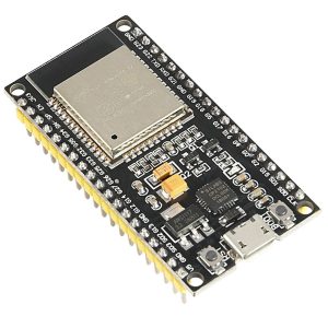
STM32F103C8T6 ARM Board
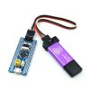
Unlike our competitors, our STM32F103C8T6 ARM Board is manufactured with a redesigned assembly that allows the controller to be readily programmed via the included USB interface. A diverse range of power-saving modes enables the development of low-power applications. Therefore, the STM32F103C8T6 ARM Board is ideal for students who want to learn about the STM32 microcontroller with an ARM Cortex-M3 32-bit core.

Having a double pin, but the pin does not default welding, the user can choose their own welding direction based on their own application cases.
Key Product Features:
- The STM32F103C8T6 ARM Board is built on the most fundamental MCU circuit, an 8M and 32768 crystal circuit, and a USB power supply circuit.
- The core board is separated into two rows, which connect to all of the I / O ports.
- The simple and convenient debugging speed with SWD simulation debug download interface.
- Using the Mirco USB interface, you can perform USB communication and power supply, as well as a USB interface, which is compatible with the standard Andrews mobile phone charging interface.
- Epson RTC crystal, easy to start, more stable.
Chip Specifications:
- Model: STM32F103C8T6.
- Core: ARM 32 Cortex-M3 CPU.
- Debug Mode: SWD.
- Working frequency: 72 MHz
- Flash Memory: 64K,
- SRAM: 20K
- Supply, I/O: 2.0-3.6 V
- Reset: (POR/PDR).
- Crystal: 4-16 MHz.
- Size: 5.3 cm x 2.2 cm.
Interface description:
- SWD interface: simulation, download, and debug support.
- Mirco USB interface: power supply and USB connectivity, but no download support.
- USART1 interface: The USART1 can be used to download the application or for communication.
- MCU pin interface: leads all I/O port pins, making it simple to connect to peripherals.
- Power input and output interfaces of 5V and 3.3V are widely utilized in external power supplies or conjunction with other modules for common ground treatment.
Other Device Description:
- Power LED (PWR): A power indication that indicates whether or not the power supply is stable.
- The user LED (PC13): to aid in the I/O output test or to signal that the program is running.
- Begin leaping Select a programming mode: 1 is the user flash memory, 2 is SRAM, and 3 is system memory.
- Reset button: resets the user program’s chip.
- 8M Crystal: The frequency of the system can be set to 72MHz.
- 6,32.768KHz Crystal: Available for use with the built-in RTC or calibration.
STM32F103C8T6 Differs From STM32F103C6T6:

| Brand Name | MINGYUANDINGYE |
|---|---|
| Origin | Mainland China |
| Condition | New |
| Type | Voltage Regulator |
| Supply Voltage | 1 |
| Dissipation Power | 1 |
| is_customized | Yes |
| Application | Computer |
Related products
Electronic Modules
Electronic Modules
Electronic Modules

Electronic Modules

Electronic Modules
Electronic Modules

Electronic Modules
Electronic Modules